
TFT Shows a White or Blank Screen: a Hardware Checklist
A white screen is usually good news: the backlight works and the panel is powered, but the driver IC never received a valid initialization. A black screen with no glow points at the backlight circuit instead. Work through the checks below in order - on the boards engineers send us, the fault is almost always in the first four, and almost never in the glass.
Written by the Junxian applications engineering team. Figures quoted for “our models” are calculated from the 103 models on this site that carry a full parameter set, so they change when the catalogue changes.
First, read the symptom correctly
White and evenly lit: backlight on, driver IC not initialised - look at reset, SPI wiring and the init sequence. Completely dark with no glow at an angle: backlight supply - look at LEDA/LEDK and the driver current. Dark but faintly showing an image under a torch: image is there, backlight is not. Random coloured noise: the controller's RAM was never cleared - it initialised but was not written. Each symptom removes half the suspects, so spend ten seconds naming it before touching anything.
Backlight and logic are two separate supplies
A TFT module carries at least two power paths: the logic rail that runs the driver IC, and the backlight LED string, which on white-LED panels needs its own current-limited supply - the anode voltage is set by how many LEDs sit in series, not by the logic rail. Powering the logic while underdriving the backlight gives a readable-under-torchlight screen; powering the backlight with a held-low reset gives the classic pure white. Check both rails with a meter at the connector, not at the regulator.
| Driving voltage | Models |
|---|---|
| 3.3V | 49 |
| 5.0V | 17 |
| 3.0V | 5 |
| 3.6V | 3 |
| 3.3V + 5.0V | 3 |
| 3.2V | 2 |
| 5V | 2 |
| 6-25V | 2 |
| 5.0V/3.3V | 1 |
| 9-60V | 1 |
| 3.1V | 1 |
| 2.8V-3.2V | 1 |
| 25.2-29.7V | 1 |
| 5V/3.3V | 1 |
| 2.8V~3.3V | 1 |
| 2.8~3.3V | 1 |
| 12.8V | 1 |
| 2.8V | 1 |
Logic supply as specified per model. The 9-60 V entries are smart serial modules built to sit directly on a battery or charger rail without a separate regulator.
Reset timing: the most common init killer
Driver ICs specify a minimum reset pulse and a wait after release before commands are accepted, and a further delay after sleep-out before the display turns on. Development boards that tie RST to the MCU reset line violate this quietly: the MCU starts sending init commands while the controller is still waking. Drive RST from a GPIO, hold it low deliberately, release it, wait, then start the sequence - and if your library has a reset-delay setting, do not shorten it to speed boot.
The FPC connector: check it before you check your code
On assembled prototypes and small production runs, the single most frequent cause we see is mechanical: the flex cable seated at a slight angle, not pushed fully home, or the ZIF latch left open. A connector that is one contact off can still power the backlight - which produces a very convincing white screen. Reseat the cable square-on, close the latch, and inspect the contact edge for wear; a flex that has been cycled many times during debugging is a legitimate suspect on its own.
“It works when I press the screen”
If the image appears or stabilises when a finger presses the glass or the cable, you have a contact or grounding problem, not a software problem: pressure is completing a marginal joint - typically the FPC contacts, a dry solder joint on the connector, or a missing ground return that your hand is providing. It will get worse with temperature and vibration, so treat it as a hard fault. The same applies to displays that only misbehave when a motor or relay switches nearby: that is a grounding and routing issue on the host board.
VCOM and gamma: faint, washed-out or negative images
When the panel shows an image but it is faint, ghosting badly, or looks like a photographic negative, the init sequence is running but its analogue settings do not match the glass: VCOM, power-control and gamma registers are copied from a different panel's example code. These values are per-glass, not per-controller - two panels on the same ST7789 can need different VCOM settings. Use the init table supplied for the exact module rather than one found for the controller name.
Proving it is the panel - and what to do then
Before concluding the module is dead: try a known-good module on the same board, and the suspect module on a known-good board or a bare dev kit. Those two swaps separate board faults from panel faults in minutes. If the module really is at fault, tell us the model, batch and symptom - init settings are confirmed per glass batch on our side, and if a batch issue is suspected we would rather hear about it at one sample than at one thousand units.
TFT modules these checks apply to
Published models that illustrate the point above - full specifications on each page.
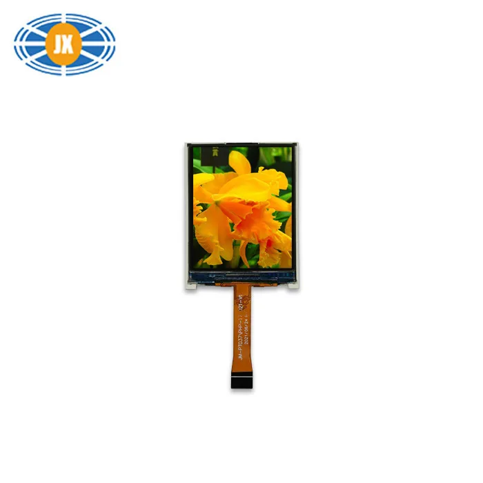
1.77 Inch TFT LCD Display 4 Bit 128×160 Pixels Color TFT Display SPI I
JM-PT037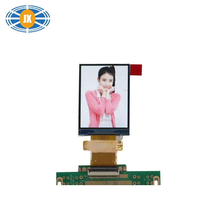
Custom 2.4 Inch TFT LCD Display 240×320 MCU Interface 350cd/m2 High Br
JM-PT090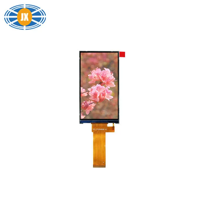
300cd/m2 5 Inch TFT LCD Monitor , IPS LCD Display Module 480x854 Pixel
JM-PT128-00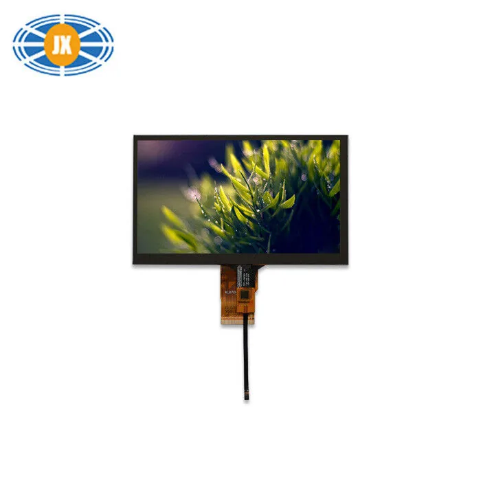
300cd/m2 High Brightness LCD Display 7 Inch 1024x600 For Automotive
JM-PT034Related guides
ST7789 / GC9A01 / ST7735 Init Problems: Offset, SPI Mode and CS
These three controllers sit behind most small SPI colour displays, and most “my display shows garbage / a shifted image / nothing”...
Driver ICs We Use, and Why the Controller Matters to Your Firmware
The driver IC is the part your firmware actually talks to. It sets the initialisation sequence, the command set, the addressing mo...
LCD Interfaces Explained: SPI, MCU, RGB, LVDS and MIPI
The interface is the first decision, not the last: it decides whether your processor can drive the panel at all, how many pins the...
Questions engineers ask us about this
Why is my TFT display white as soon as power is applied?
Because the backlight is a separate circuit that needs no initialisation - it lights the moment it has current. White means “backlight yes, valid pixel data no”: the driver IC has not been initialised or is not receiving data. Reset timing, SPI wiring and the init sequence are the suspects, in that order.
The display worked yesterday and is white today. What changed?
If the code did not change, the connection did: FPC seating, a fatigued flex, or a dry joint that finally opened. Reseat the cable first. A module that recovers when flexed or pressed has a mechanical fault, not a software one.
Can a wrong init sequence damage the panel?
The realistic risk is not the command table but the analogue settings and the backlight: overdriving backlight current shortens LED life, and grossly wrong power-control settings can stress the glass over time. A wrong command table normally just gives a wrong picture - fix it and the panel is fine.
How do I tell a dead backlight from a dead panel?
Shine a torch at an angle onto the powered screen. If you can see the image faintly, the panel and controller are working and the backlight circuit is not. If there is nothing at all, go back to logic supply and initialisation.
Do you provide the correct init code for your modules?
Yes - ask with the model number and we supply the initialisation sequence verified for that module and batch, including reset timing and the VCOM/gamma values matched to the glass. If you are migrating from another panel, send your existing init table and we will mark what must change.
Need a quote or a datasheet?
Send us size, resolution, interface and annual quantity. Our engineers reply within one working day. Sample MOQ 5 pcs, lead time 10-20 days.