
FPC, Backlight and PCBA: What Can Be Changed Without New Glass
Most display customisation happens around the glass, not in it. FPC length, pin order and exit direction, connector, backlight brightness and colour, driver selection and the PCBA are all changeable on an existing panel at 100 pcs with no mask and no tooling. Knowing that boundary is worth money: it is the difference between a 100 pcs order in 10-20 days and a tooled part at 1,000 pcs.
Written by the Junxian applications engineering team. Figures quoted for “our models” are calculated from the 103 models on this site that carry a full parameter set, so they change when the catalogue changes.
What can be changed without tooling
Here is the whole boundary in one table - find your change and you have your MOQ tier and roughly your schedule.
| Change | Needs tooling? | MOQ tier | What to watch |
|---|---|---|---|
| FPC length, pin order, exit direction | No | 100 pcs | Cable and layout change on your side only |
| Connector type | No | 100 pcs | Confirm mating part and pitch on the drawing |
| Backlight brightness or colour | No | 100 pcs | Affects power budget and lifetime |
| Touch panel added or changed | Sensor may need tooling | 100 pcs - 1,000 pcs | Existing sensor pattern keeps you in the lower tier |
| Cover glass outline and printing | Yes, cover glass tooling | 100 pcs | Quoted per drawing |
| Driver IC selection | No, within what the glass supports | 100 pcs | May change the init sequence in firmware |
| Smart module firmware and screen layout | No | 100 pcs | Applies to UART smart modules |
| New glass size or outline | Yes, mask | 1,000 pcs | Tooling quoted as a separate line |
| Non-rectangular or round glass | Yes, mask | 1,000 pcs | Confirm visible area against the bezel first |
| Custom segment layout | Yes, mask | 1,000 pcs | Send the layout or a photo plus a sketch |
FPC: the change people request most
Length, pin order, exit direction and stiffener position are all open. Two things to decide on the drawing rather than at the sample stage: which way the tail leaves the module relative to your board, because a tail that exits the wrong side turns into a fold that stresses the bond; and the bend radius, because an FPC folded tighter than it likes fails after thermal cycling rather than immediately - the worst kind of failure, because it passes your prototype test. Send the mechanical drawing with the board position marked and this becomes a five-minute conversation.
Backlight: brightness, colour and drive
Brightness is set by LED count and drive current, and both are adjustable within what the light guide supports. On monochrome character and segment modules the backlight colour is a genuine choice - white, blue, yellow-green, amber, red - with no cost difference between most of them, which makes it free branding. On colour panels the backlight is white by design. What to tell us: the brightness you need at the dimmest usable setting, whether it is PWM or analogue dimmed, and the supply available - the driver follows from those three.
Driving voltage across our range
Most modules are 3.3 V or 5 V logic. The outliers are worth knowing about, because they remove a regulator from your board:
| Driving voltage | Models |
|---|---|
| 3.3V | 49 |
| 5.0V | 17 |
| 3.0V | 5 |
| 3.6V | 3 |
| 3.3V + 5.0V | 3 |
| 3.2V | 2 |
| 5V | 2 |
| 6-25V | 2 |
| 5.0V/3.3V | 1 |
| 9-60V | 1 |
| 3.1V | 1 |
| 2.8V-3.2V | 1 |
| 25.2-29.7V | 1 |
| 5V/3.3V | 1 |
| 2.8V~3.3V | 1 |
| 2.8~3.3V | 1 |
| 12.8V | 1 |
| 2.8V | 1 |
Logic supply as specified per model. The 9-60 V entries are smart serial modules built to sit directly on a battery or charger rail without a separate regulator.
PCBA and smart modules
Where a module carries a PCB, the board itself is customisable: connector placement, level shifting, an on-board regulator so you can feed it a raw supply, or a controller with your command set on smart serial modules. This is where a display supplier can remove work from your hardware team rather than adding it - if your board is doing level shifting and power conditioning purely to feed the display, that belongs on the module.
Cover glass and bonding sit at the boundary
Cover glass outline, thickness, printing and hardening are per-project items - tooled, but cover-glass tooling rather than a glass mask, so they stay in the 100 pcs tier. A new touch sensor pattern is the point where you cross into 1,000 pcs. If you are close to that line, ask us before finalising the artwork: adapting a design to an existing sensor pattern is often invisible in the finished product and materially cheaper.
What we need to quote a modification in one round
The base model (ours or the one you use now), the mechanical drawing with the FPC route and connector position, the supply voltage available, the brightness at nominal drive, and the annual quantity. Missing the drawing is what turns a one-round quotation into three.
Models most often ordered with modifications
Published models that illustrate the point above - full specifications on each page.
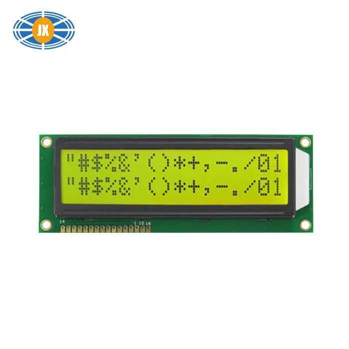
LCD 16x2 Alphanumeric Display 16 PIN Flexible LCD Modules With Multi C
JM1602M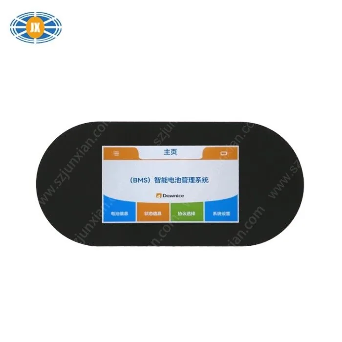
4.3 Inch BMS Serial Port Capacitive LCD Touch Screen 5V Full View Clea
JM-LH018-00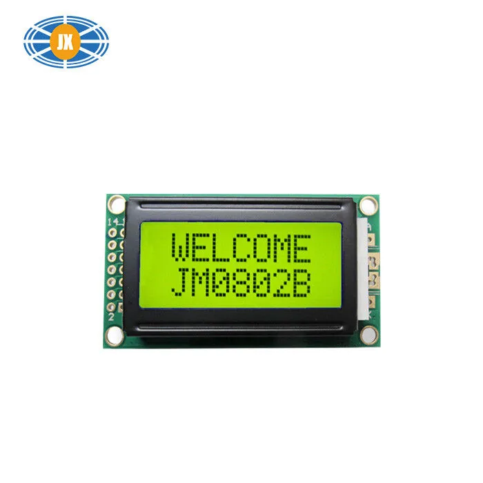
8x2 Character LCD Module ST7066 Blue Monochrome LCD Display Multiple S
JM0802B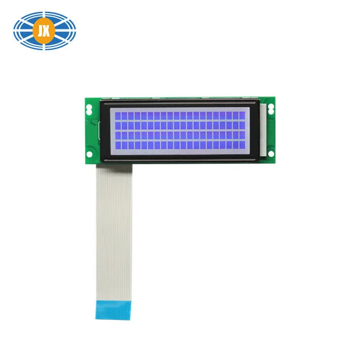
3.2 Inch Character LCD Modules High Contrast LCD Display 100cd/m2 With
JM-2004C-00Related guides
How a Custom LCD Module Is Developed, Step by Step
Most 'custom' display projects are not custom glass at all - they are an existing panel with a different FPC, connector, backlight...
Driver ICs We Use, and Why the Controller Matters to Your Firmware
The driver IC is the part your firmware actually talks to. It sets the initialisation sequence, the command set, the addressing mo...
LCD Module MOQ, Lead Time and Sample Policy
Samples 5 pcs. Catalogue models 100 pcs. Fully custom tooled glass 1,000 pcs. Production lead time 10-20 days, samples 10-15 days....
Questions engineers ask us about this
Can you change the FPC length and pin order?
Yes - one of the most common modifications, no glass tooling, 100 pcs. Send the mechanical drawing with the board position and we will confirm the routing on the outline drawing before samples.
Can I choose the backlight colour?
On character and segment modules yes - white, blue, yellow-green, amber and red are standard and mostly cost the same. On colour TFT the backlight is white by design and the UI carries the brand colour.
Can the module accept my supply voltage directly?
Often yes, with an on-board regulator on the module PCB. Some of our smart serial modules already run from a 9-60 V rail for exactly this reason. Tell us your supply and we will say whether it needs a change or an existing part covers it.
What is the MOQ for these changes?
100 pcs for anything that reuses existing glass - FPC, connector, backlight, driver selection, PCBA, cover glass. 1,000 pcs once new glass or a new touch sensor pattern has to be tooled.
How long does a modified module take?
10-15 days for samples and 10-20 days for production, same as a catalogue part, because no tooling is involved. The schedule risk is the drawing approval cycle, not the factory.
Need a quote or a datasheet?
Send us size, resolution, interface and annual quantity. Our engineers reply within one working day. Sample MOQ 5 pcs, lead time 10-20 days.